TECHNOLOGY
The company has rich management and operation experience, strong technical force, advanced production technology,
sophisticated production equipment, complete testing methods, reliable product quality, and thoughtful after-sales service.
Principle and Application of Double Closed Loop DC Speed Control Module
- Categories:Technical Support
- Author:
- Origin:
- Time of issue:2013-05-27
- Views:0
(Summary description)4. Concluding remarks The system is designed in the form of modules: high integration, small size, convenient wiring, simple adjustment, safe and reliable operation, and versatility, that is, the same module has the same parameters and is very convenient to use.
Principle and Application of Double Closed Loop DC Speed Control Module
(Summary description)4. Concluding remarks The system is designed in the form of modules: high integration, small size, convenient wiring, simple adjustment, safe and reliable operation, and versatility, that is, the same module has the same parameters and is very convenient to use.
- Categories:Technical Support
- Author:
- Origin:
- Time of issue:2013-05-27
- Views:0
I. Introduction:
Thyristor DC drive has been vigorously promoted and applied in our country around the 1970s. After more than 30 years of development history, it still stays on the basis of discrete devices, with large volume, complicated wiring, extremely inconvenient use and expensive. The dual closed-loop DC speed control module developed by our company modularizes the DC speed control system based on the principle of integration and ease of use. The advanced technological process and high-performance circuit design greatly improve the service life and reliability of the module, and the cost performance is very high, which adds new vitality to the field of DC speed regulation.
2. Circuit configuration inside the module
This module contains power thyristor, phase shift control circuit, speed current double closed loop speed regulation circuit, integration circuit, current feedback circuit, and phase loss and overcurrent protection circuit. The block diagram is shown in Figure 1.
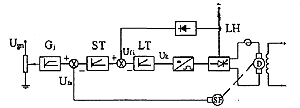
figure 1
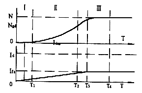
figure 2
(1) The power thyristor completes the conversion and power adjustment. It adopts imported square chips and advanced chip support plates. After a special sintering process, the solder layer is guaranteed to be free of voids. The use of DCB boards and other advanced thermal conductivity insulating materials has good thermal conductivity and the substrate is not charged. , The use is safe and reliable. The number of thermal cycles exceeds the national standard by nearly 10 times, and it has a long service life.
(2) The integral link can realize the soft start of the DC motor, and the starting time can be adjusted. Two ports are reserved for the user during the design. The connection is shown in Figure 6. Adjusting the two potentiometers can change the length of the integral time to change the motor The purpose of the start time. The integration link is suitable for occasions where the starting transition process is stable, such as blast furnace hoist, mine hoist, cold and hot continuous rolling mill, etc. When the input is a step signal, it is transformed into a linear gradual output signal with a certain slope by the given integrator, which is used as the given input of the speed regulator. The stable output of the given integrator is the given speed of the motor. The change slope of the integrator output is the acceleration of the motor, and the starting current waveform is shown in Figure 2. If the user requires the motor to start with the maximum constant acceleration under certain load conditions, the integral link can be removed, and the module sets aside two ports as the output limiter of the current loop and speed loop (as shown in Figure 6) to adjust the current loop The output is limited to change the maximum starting current of the motor to obtain an ideal transition process. The starting current waveform is shown in Figure 3.
(3) Speed current double closed loop circuit Speed regulation and resistance to load and grid disturbance, using double PI regulators, can obtain good dynamic and static effects. The design process adopts the "second-order best" parameter design method to select the best parameters combined with the dynamic and static effects of the system. From the viewpoint of suppressing overshoot, the current loop is corrected to a typical I-type system. In order to make the system have no steady-state error during step disturbance and have better anti-disturbance performance, the speed loop is designed as a typical type II system.
Comparison of the logarithmic amplitude-frequency characteristics of the inner and outer loops, Figure 4 shows the open-loop logarithmic amplitude-frequency characteristics of the current loop and the speed loop:
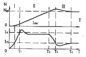
image 3
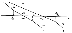
image 4
It can be seen from the figure above that the turning frequency and cutoff frequency points in the figure are smaller than one, which is an inevitable law. In a double-ring system designed in this way, the outer ring is always slower than the inner ring. Generally speaking, the adjustment process is generally the outer loop first and then the inner loop. To improve the dynamic effect of the system, the current loop can increase the resistance of the current loop's resistance-capacitance terminal, but to reduce the capacitance, the relationship is C1*0.03/R1. In order to improve the dynamic effect of the speed loop, it is obtained from the various indicators of a typical Type II system that its dynamic effect is an intermediate parameter, which needs to be repeatedly adjusted. Increasing the resistance R2 can improve the steady-state accuracy of the system, and reduce it accordingly. A small resistance can obtain a good dynamic effect. The specific situation can be adjusted according to the user's system parameter requirements. The relationship is C2 0..87/R2 (current overshoot <=5). The module design process leaves four ports (its The connection is shown in Figure 6), as the RC terminal of the speed loop and the current loop, the user can adjust it according to the actual situation.
(4) Current feedback It adopts imported Hall sensor from abroad and is placed inside the module. It mainly completes the sampling of current signal, which has extremely high linearity and simplifies the peripheral components of the system.
(5) The protection circuit module is equipped with overcurrent and phase loss protection circuits to ensure the safe operation of the motor, and a port is set aside as the overcurrent protection given signal input (the connection is shown in Figure 6). Overload capacity adjustment highlights the flexibility of this module.
3. Module application
Current and speed double closed loop speed regulation circuit, because of its extremely high speed regulation range, good dynamic and static performance and anti-disturbance performance, it has been widely used in the field of speed regulation.
This module is applied to papermaking, extrusion, printing and dyeing and other DC speed regulation fields, and the effect is very good.
Experimental conditions: The module is MSZ-ZLTS-400, DC motor: Ued=220V, Ied=41A, Ned=1500r/min, and the allowable overload multiple is 1.5.
Experimental results: speed overshoot Vp<5%, current overshoot Ip<0.5%, adjustment time Ts<0.5S, number of oscillations H<=2, speed stability Vb<=0.02, speed stability Vs<0.5% (Picture 5)
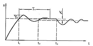
Figure 5
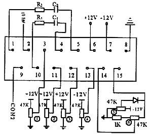
Figure 6
4. Concluding remarks The system is designed in the form of modules: high integration, small size, convenient wiring, simple adjustment, safe and reliable operation, and versatility, that is, the same module has the same parameters and is very convenient to use.

Yinhe High-Tech Development
MESSAGE
- After-sales service
- Hotline +86-533-7216217
- Top
Copyright 2020 Zibo Linzi Yinhe High-Tech Development Co., Ltd. 鲁ICP备12000870号 Powered by www.300.cn
