ABOUT US

Zibo Linzi Yinhe High-Tech Development Co., Ltd. is located in Linzi District, Zibo City, the birthplace of world football and the ancient capital of Qi State. It was established in February 1993. ), a high-tech enterprise integrating research, design, production and sales of power electronic devices, with a number of domestic leading technologies and independent intellectual property rights. The company occupies an area of 20,000 square meters, has a registered capital of 21.8 million yuan, 125 employees (including more than 30% of technicians), advanced technology and equipment, and has strong technical research and development capabilities and large-scale production capabilities.

1993Year

Company was founded

27Years

Experience in the field of ceramic copper clad laminates

21.8Million Ruan

Registered Capital

20000

Company Area

125+

Existing Senior Staff

The company has rich management and operation experience, strong technical force, advanced production technology, sophisticated production equipment,

complete testing methods, reliable product quality, and thoughtful after-sales service
OUR PRODUCTS

Smart power regulator

Smart power regulator

Double closed loop DC speed control board

Double closed loop DC speed control board

Capacitor switching control board

Capacitor switching control board

Plating electrolysis power control cabinet

Plating electrolysis power control cabinet

Electrophoresis power control cabinet

Electrophoresis power control cabinet

AC motor soft starter

AC motor soft starter

Frequency converter

Frequency converter

Constant pressure precision control super audio frequency induction heating equipment

Constant pressure precision control super audio frequency induction heating equipment

Some application examples of heating equipment

Some application examples of heating equipment

Prev
Next

We focus on the fields of high-power power electronic capacitors and induction furnace capacitors, and our products have been recognized by customers in many fields

Bridge Rectifier Module

Smart grid flexible DC transmission converter valves, circuit breakers, etc.

Solid State Relay

Widely used in various non-isolated electrical switch occasions such as temperature control and light control

Double closed loop DC speed control module

Application of DC speed control panel/double closed loop DC

Constant current and constant voltage control

module

Battery charging, inverter

discharge

NEWS

NEWS

Congratulations to General Manager Li Lei for winning the title of "Young and Middle-aged Experts with Outstanding Contributions in Linzi District".

Congratulations to General Manager Li Lei for winning the title of "Young and Middle-aged Experts with Outstanding Contributions in Linzi District".

Congratulations to General Manager Li Lei for winning the title of "Young and Middle-aged Experts with Outstanding Contributions in Linzi District".
Congratulations on the selection of ceramic copper clad laminate products into the national "Blue Book of Power Electronic Device Industry Development (2016-2020)"

Congratulations on the selection of ceramic copper clad laminate products into the national "Blue Book of Power Electronic Device Industry Development (2016-2020)"

Excerpted from the national "Blue Book on the Development of Power Electronic Devices Industry (2016-2020)" on the key points of power electronics development in 2016-2020 As we all know, the manufacturing industry is the main body of the national economy, the foundation of the nation, the tool of rejuvenation, and the foundation of a strong nation. Without a strong manufacturing industry, there would be no country and nation's prosperity. As one of the manufacturing industries, the power electronic device industry is a high-tech basic industry related to the national economy and people's livelihood, and it plays an important role in economic development, national defense construction and people's livelihood. The power electronic device industry is mainly the production of core power electronic chips and packaging, but it is also inseparable from the support of semiconductor and electronic materials, key components, manufacturing equipment, testing equipment and other industries. Its development requires both the upstream basic material industry Support requires the pull of the downstream device industry, and its industrial development is characterized by large investment and long cycle. In order to establish my country's independent and internationally competitive power electronic device industry, it is recommended to focus on the following technologies and industries from 2016 to 2020, and formulate relevant technical standards for key materials. Among them, the short-term development goals are: 1. Material of key parts (1) Develop materials for precision ceramic structural parts of flat-panel fully-crimped multiple racks to meet the needs of flat-panel fully-crimped IGBT manufacturing. (2) Development of alumina (Al2O3) ceramic copper clad laminates, aluminum nitride (AlN) ceramic copper clad laminates, silicon nitride (Si3N4) ceramic copper clad laminates, aluminum-silicon carbide (AlSiC) substrates, silicon gels, soldering sheets (welding (Belt) and other key parts and materials to meet the needs of welding power module manufacturing. 2. Key material technical standards It is recommended to develop flat-plate full crimping multi-bench precision ceramic structural parts, aluminum oxide (Al2O3) ceramic copper clad laminate (DBC and AMB process), aluminum nitride (AlN) ceramic copper clad laminate (DBC and AMB process), silicon nitride (Si3N4) ) Technical standards for ceramic copper clad laminates, aluminum-silicon carbide (AlSiC) substrates, silicone gels, solder tabs (strips) and other key component materials. During the “Twelfth Five-Year Plan” period, my country’s power electronic device market accounted for an increasing share of the global market, and it has become the world’s largest demand market for high-power power electronic devices. During this period, the annual growth rate of my country’s power electronic device market is nearly 20%. However, we must realize that the import rate of my country's IGBT chips is still high, and the main market is still dominated by foreign companies, which seriously hinders the healthy development of my country's independent IGBT device industry. Therefore, as the core of the power electronic device industry, the development of key materials involved in the production of power electronic chips and packaging is particularly important. It plays a pivotal role in establishing my country's independent and internationally competitive power electronic device industry.
Congratulations to Zibo for being included in the first batch of national industrial transformation and upgrading demonstration zones

Congratulations to Zibo for being included in the first batch of national industrial transformation and upgrading demonstration zones

Zibo has been identified as one of the first national demonstration zones for industrial transformation and upgrading of old industrial cities and resource-based cities. There are only 12 demonstration zones in the country! Today, the National Development and Reform Commission website announced this news, and this also means that Zibo City It will receive strong support in industrial policy, innovation policy, investment policy, financial policy, land policy, etc. 12 industrial transformation demonstration zone Zibo among them In order to implement the decision and deployment of the Party Central Committee and the State Council on the comprehensive revitalization of old industrial bases in Northeast China, in accordance with the "Implementation Opinions on Supporting the Industrial Transformation and Upgrading of Old Industrial Cities and Resource-based Cities" and "Industrial Transformation and Upgrading of Old Industrial Cities and Resource-based Cities" The Measures for the Administration of Demonstration Zones, the National Development and Reform Commission, the Ministry of Science and Technology, the Ministry of Industry and Information Technology, the Ministry of Land and Resources, and the China Development Bank jointly issued the “Notice on Supporting the Construction of the First Batch of Demonstration Zones for the Industrial Transformation and Upgrading of Old Industrial Cities and Resource-based Cities” (hereinafter referred to as the “Notice”) ) And identified 12 cities (economic zones) as the first batch of demonstration zones for industrial transformation and upgrading. The 12 cities (economic zones) are central Liaoning (Shenyang-Anshan-Fushun), central Jilin (Changchun-Jilin-Songyuan), western Inner Mongolia (Baotou-Ordos), Tangshan, Hebei, Changzhi, Shanxi, Zibo, Shandong, and Tongling, Anhui , Huangshi, Hubei, Central Hunan (Zhuzhou-Xiangtan-Loudi), Chongqing Central Metropolitan Area, Zigong, Sichuan, northeastern Ningxia (Shizuishan-Ningdong). It is reported that these 12 cities (economic zones) are all typical old industrial cities specified in the National Old Industrial Base Adjustment and Reconstruction Plan (2013-2022) and the National Resource-based City Sustainable Development Plan (2013-2020) And resource-based cities have been recommended by their respective provincial people’s governments to apply for the construction of demonstration zones. These cities have carried out a lot of work in the field of industrial transformation and upgrading in recent years. Compared with similar cities in the country, they have good basic conditions, strong work intensity, practical reform and innovation measures, and obvious demonstration effects. They have initially formed a group of promoting industrial transformation and upgrading. Typical empirical approach. Supporting the construction of demonstration zones for industrial transformation and upgrading in these cities is conducive to promoting the economic transformation and development of these cities (economic zones) and deepening supply-side structural reforms, helping to improve the level of industrial intensive development of these cities (economic zones) and improving these cities (Economic Zone) The quality and benefits of economic development are conducive to demonstration, typical guides, point-to-point, and first breakthroughs, and explore experiences for the transformation and development of similar cities across the country. The five departments will increase their support to the demonstration area According to the requirements, the people’s government of the city where the demonstration area is located should take the construction of the demonstration area as a major task to promote urban transformation and development, improve the working mechanism in accordance with local conditions, improve the work organization, decompose work tasks, implement work responsibilities, and actively explore and accelerate the demonstration area and New mechanism and new method of demonstration park construction. Relevant departments of all provinces (autonomous regions and municipalities) should promptly revise and improve the construction plan of the demonstration zone based on expert review opinions, and report to the provincial people’s government for approval before printing and implementing, and copying to the five departments. It is necessary to combine construction plans to guide various demonstration zones to steadily advance relevant work, accelerate the establishment of an innovation-driven industrial transformation and upgrading endogenous power mechanism, form a platform support system with parks as the core carrier, and build modern industrial clusters with distinctive characteristics and strong competitiveness. At the same time, the five departments will increase their support for the construction of demonstration zones and demonstration parks in terms of industrial policies, innovation policies, investment policies, fina
Good news: The latest product of Zibo Linzi Yinhe High-Tech Development Co., Ltd.-Thyristor Voltage Regulator

Good news: The latest product of Zibo Linzi Yinhe High-Tech Development Co., Ltd.-Thyristor Voltage Regulator

Good news: The latest product of Zibo Linzi Yinhe High-Tech Development Co., Ltd.-Thyristor Voltage Regulator
Good news: The latest product of Zibo Linzi Yinhe High-Tech Development Co., Ltd. is on the market-battery charging and discharging control panel

Good news: The latest product of Zibo Linzi Yinhe High-Tech Development Co., Ltd. is on the market-battery charging and discharging control panel

Good news: The latest product of Zibo Linzi Yinhe High-Tech Development Co., Ltd. is on the market-battery charging and discharging control panel
The company participated in the Guangzhou International Lighting Exhibition

The company participated in the Guangzhou International Lighting Exhibition

The company participated in the Guangzhou International Lighting Exhibition Address: No. 380 Yuejiang Middle Road, Haizhu District, Guangzhou City 13.2 Hall G30 Date: 2013.06.09-2013.06.12 welcome new and old customers to come and visit.
The company participated in PCIM ASIA Power Electronics Smart Sports Renewable Energy and Energy Management International Exhibition and Seminar
The company participated in PCIM ASIA Power Electronics Smart Sports Renewable Energy and Energy Management International Exhibition and Seminar

The company participated in PCIM ASIA Power Electronics Smart Sports Renewable Energy and Energy Management International Exhibition and Seminar Exhibition address: Booth 623, Hall 4, Shanghai World Expo Exhibition & Convention Center Exhibition Hall Address: 1099 Guozhan Road, Shanghai Date: 2013.06.18-2013.06.20 welcome new and old customers to come and visit.
Application of Thyristor Intelligent Control Module
Application of Thyristor Intelligent Control Module

Circuit description: Use the thyristor intelligent control module as the power adjustment part, plus closed-loop control, according to the actual situation can be made into various power supplies with various functions to meet different needs. Applications: Widely used in DC motors, generator excitation, DC screens (battery charging), laser power supplies, magnetizing equipment, UPS power supplies, etc. The above are the main application directions of our company's modules for reference. There are still wider application prospects in other fields, such as reactive power compensation equipment, ultrasonic instruments, etc.
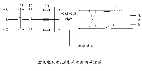
Constant current and constant voltage control module application
Constant current and constant voltage control module application

Circuit description: The steady current and voltage stabilizing circuit is integrated inside the module, the peripheral components are simple, and the output voltage is continuously adjustable. Application areas: Widely used in DC motors, generator excitation, battery charging, laser power supplies, energy-saving street lamps, arc welding machine power supplies, magnetizing equipment, UPS power supplies, etc.
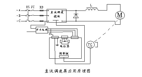
Application of double closed loop DC speed control module

Application of double closed loop DC speed control module

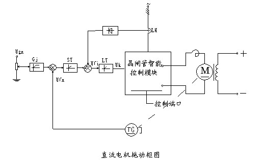
Circuit description: The applied power of plastic extruder is generally about 80%, and it is required to have hard mechanical properties at low and high speeds. The DC speed control module adds a smoothing reactor to the output anode, and a freewheeling diode between the anode and the cathode. Adding a reactor can achieve harder mechanical characteristics and current continuity effects. Features: easy installation, maintenance-free, and high reliability.
Solid state relay application

Solid state relay application

Product use: Widely used in various non-isolated electrical switch occasions such as temperature control and light control. Features: adopts zero-crossing trigger form; wide control voltage range; adopts imported square chip, advanced chip support board, through special sintering process, to ensure that the soldering layer has no voids and is more reliable in use; adopts DCB board and other advanced thermal insulation materials, thermal conductivity Good, the bottom plate is not charged to ensure safe use; the number of thermal cycle loads exceeds the national standard by nearly 10 times, and the service life is long. Application areas: color expansion, printing equipment, injection molding machinery, air-conditioning temperature control; various types of packaging machinery; various motor drives (forward and reverse control); printers, automatic washing machines, refrigerators; signal lights, traffic lights, flashers Etc.; stage light control, lighting; industrial automation control; temperature control, kiln automation control; computer embroidery machine, currency counter, postal sorting machine; computer music fountain; TSC static reactive power compensation; single three-phase contactless power switch.
Bridge rectifier module application

Bridge rectifier module application

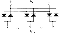
Product Usage: is widely used in electrolysis, electroplating, excitation and various DC power applications. Features: high power, small size, convenient wiring; imported chips, advanced chip support board, special sintering process to ensure that the soldering layer has no voids and more reliable use; DCB board and other advanced thermal insulation materials, good thermal conductivity, bottom plate No electricity (except MDY series modules), to ensure safe and convenient use. The heat cycle load times exceed the national standard by nearly 10 times, and the service life is long. Application areas: Various rectifier power supplies; electric welding machines, motor excitation power supplies; electroplating and electrolysis power supplies.
Quick reference to basic technical data of thyristor series module products

Quick reference to basic technical data of thyristor series module products

2. The constituent materials in the module The component materials of the module: Thyristor, DCB (Ceramic Copper Clad Laminate), phase shift trigger control circuit, (protection circuit, feedback circuit, current, voltage sensor, single-chip microcomputer and above are included in the functional module) heat dissipation base plate, input and output electrodes, control signal Port and other components. 3, the chip used inside the module uses imported glass passivation square chip, produced in Germany. The chip withstand voltage of the module is 1200-2200V 4. Introduction to the internal insulation of the modules The isolation method in the module is: the thyristor and the heat dissipation base plate are separated by a DCB ceramic copper clad plate, the dielectric strength VISO≥2500VAC, the trigger circuit and the thyristor main circuit are electromagnetically isolated. The dielectric strength between them is ≥2000V. It is protected by elastic silicone gel and sealed with epoxy resin. 5, the circuit form of the module According to the needs of the load, the main circuit design of the thyristor mainly includes four circuit forms: three-phase rectification, three-phase AC, single-phase rectification, and single-phase AC. 6. What is the temperature coefficient of the output voltage of the module? The temperature coefficient is 600PPM/℃. 7. What is the rate of increase of the current (di/dt) and voltage (dv/dt) of the module? Current rise rate: 100A/μS 500V/μS 8. Whether there is protection function in the module Ordinary thyristor modules generally do not have protection inside. Functional products such as constant current and constant voltage control modules, intelligent motor control modules, and dual closed-loop DC speed control modules have overcurrent, phase loss, and overheat protection functions, according to customer needs. Type modules can also be customized with various protection functions. 9. The control signal of the module ±l2V regulated power supply requirements voltage range +12V ±0.5V, ripple voltage is less than 30mv; -12V±0.5V, ripple voltage is less than 30mv; for ±12V power supply accuracy is required ±0.5V; ripple voltage ≤10mv current capability The current of the ±12V power supply must be more than 2 times the actual working current. If a transformer rectified regulated power supply is used, the filter capacitor must be greater than 1000μF/25V. 10. Will harmonics be generated when the module is working? How much is the impact? The harmonics generated by the module during operation are the same as the traditional thyristor circuit, which will have an impact on the grid, but it is not serious. It is not a superposition of harmonics and does not affect the normal operation of other equipment. 11. What is the relationship between module input voltage and output voltage? AC module Vout=0~1.0Vin, three-phase rectifier module Vout=0~1.35Vin. Single-phase rectifier module Vout=0~0.9Vin. 12. Is the module an open-loop control system or a closed-loop control system? The thyristor smart module (such as full-control rectification, AC, etc.) is an open-loop control system; functional products with functional modules (such as constant current and constant voltage control modules, intelligent motor control modules, dual closed-loop DC speed control modules, etc.) are a Closed loop control system. 13. What is the difference between the use of an open-loop module and a closed-loop module? What is the difference in control? The open-loop module changes with the load and the power grid, and the closed-loop module does not change with the change within a certain load and power grid range (power grid ±20%, load change 60%). Open-loop module control power supply uses +12V, and closed-loop module control power supply uses ±12V. 14, the thyristor trigger pulse form in the module The thyristor trigger uses a wide pulse trigger, and the trigger pulse width is about 4ms (milliseconds). 15. Is the main circuit of the thyristor module fully controlled or half controlled? Is the trigger circuit fully controlled or half controlled? What is the difference between the trigger voltage of full control and half control? What is the difference in waveform? The main circuit of the thyristor is a fully-controlled bridge, and the trigger circuit is divided into half-controlled and fully-controlled. The half-control trigger voltage is 0~10V, and the full-control trigger voltage is all on after 7V. The half-control module waveform diagram has only three thyristor waveforms in one cycle, and the full-control module waveform diagram has six thyristor waveforms in one cycle. 16. What is the isolation method between the main circuit of the module and the trigger circuit? What is the isolation voltage? There are two isolation methods. The solid state relay adopts photoelectric isolation, and the other modules adopt electromagnetic isolation, and the isolation voltage is 2500VAC. 17. Why do modules nee
Technical solutions for on-site use of thyristor series module products

Technical solutions for on-site use of thyristor series module products

(1) What is the difference between the voltage regulation function of the AC module and the transformer? The transformer can isolate the load from the grid, and transmit equal power according to the set transformation ratio; the AC module is not isolated from the grid and only regulates the grid voltage, and its transmission power is limited by the current and decreases as the voltage decreases. (2) What is the anti-interference ability of the module? The module is adapted to the large distortion of the power grid waveform, and can work normally even when the main circuit is working with high current, and the phase-shift trigger control system does not interfere with the connected computer or other control instruments, and has strong anti-interference ability. (3) What quality assurance does the module have? Products are produced in strict accordance with the company's technical standards and quality levels. If it is a quality problem of the supplier's product itself, the supplier will replace it within one year of sale. (4) Will the module generate harmonics when it is working? The harmonics generated by the module during operation are the same as the traditional thyristor circuit, which will affect the power grid, but according to the user's feedback, the impact on the power grid is relatively small. An example can be taken to illustrate this problem: the ratio of the output power controlled by the module to the power of the grid power transformer is a basis for determining the size of the impact. The grid power transformer has a relatively large capacity and can supply a larger current, while the output power of the module is relatively large compared to the transformer. If the power of the module is relatively small, its impact can be ignored; on the contrary, if the output power controlled by the module is relatively large relative to the power of the transformer, the impact will be relatively large. Power capacitors can be used to absorb when the impact is large, and LC can be used when necessary. (5) When the module is manually controlled, what are the requirements for the potentiometer used? The power of the potentiometer is ≥0.5W, and the resistance range is from 5.1 to 100K. (6) What should be paid attention to when cooling the module? The junction temperature of the module chip cannot exceed 125 degrees. When the module is working stably, the temperature of the heat sink should not exceed 80 degrees (ie the case temperature of the module), otherwise the module will be burnt out. (7) When the output of the user test module is abnormal, which aspects should be considered? 1) Whether the module has a load test. 2) Whether the 12V power supply meets the working requirements of the module. 3) If it is controlled by a microcomputer or an instrument, check whether there is a discharge circuit at the control end. Because there is a capacitor on pins 2 and 3 that may store charges, which will turn on when no signal is applied, a 500K resistor must be connected to pins 2 and 3. 4) If the user's test is unbalanced, first check whether the load is balanced, and whether the red and black test leads of the digital meter should be AB, BC, CA phase during the test. 5) Whether the wiring is correct, especially for single-phase AC modules, a neutral wire should be added to both sides. 6) If the module does not work normally when the user has inductive or capacitive load or the load is uncertain, it is recommended that the user test under pure resistive load. 7) When the control signal is uncertain, use potentiometer to adjust to check whether the module is normal.
Key insulating materials for power electronic modules
Key insulating materials for power electronic modules

In the development of power semiconductor modules, with the increase in integration and the reduction in size, the power consumption per unit heat dissipation area has increased. Heat dissipation has become a key issue in module manufacturing. The traditional module structure (welded and crimped Formula) has been unable to successfully solve the heat dissipation problem. Therefore, new requirements are put forward for the thermally conductive insulating material between the heat dissipation base plate and the chip. At present, this kind of material used in the power electronics industry at home and abroad is generally a ceramic-metal composite board structure, referred to as DBC board (Dircet Bonding Copper). The so-called DBC technology refers to the technology of directly bonding copper to ceramic materials at high temperatures. The DBC board mainly uses thermally conductive and insulating ceramic substrates such as Al2O3, AIN, and BeO. Because BeO contains toxicity, it is rarely used in industry. Although AIN has good thermal conductivity and a coefficient of thermal expansion similar to that of silicon, its price is too high. Therefore, Al2O3 has been widely used as a thermally conductive insulating substrate for DBC boards, and AIN is also under development. At present, foreign DBC substrates have been put into industrial production and are widely used in power semiconductor modules, microwave transmission and sealing and other fields. Among the power semiconductors of the same power, the welded module of the DBC board, compared with the ordinary welded module, is not only small in size, light in weight, saving parts, but also has better thermal fatigue stability and higher integration. Domestic research in this area has just started, and industrial production has not yet been formed. The Institute of Electrical Insulation, Xi’an Jiaotong University, combined with the "Eighth Five-Year Plan" task of GTR module packaging structure, used DBC technology to develop Al2O3-Cu composite boards and provided them to Xi’an Institute of Power Electronics Technology, Beijing Power Electronics New Technology Research and Development Center, etc. Unit trial. Small batch production in the laboratory has been formed. The market prospects are impressive. The role of the DBC substrate in the power module is as follows: 1) As the carrier of the silicon chip, and there is no other material and connecting wire between the two. Circuit wiring substrate, the function is similar to PCB board. 2) Good insulation performance, separate conductive parts and heat dissipation parts. 3) Good heat dissipation performance. The heat generated by the silicon chip is transferred to the heat sink through the thermal oil. Therefore, DBC substrate is a substrate with excellent thermal conductivity and insulation performance. Al2O3-Cu substrate has the following excellent characteristics: 1) The thermal resistance is small, and the thermal expansion coefficient is the same as Al2O3, which is similar to silicon (7.4×10⁻⁵K-1). No transition layer is required during use. The silicon chip can be directly soldered on the DBC substrate; 2) Has good mechanical properties, adhesion>5000N/cm2, peel resistance>90N/cm; 3) Corrosion resistance, no deformation, can be used in the temperature range of -55℃~+860℃; 4) Excellent electrical insulation performance, porcelain plate withstand voltage>2.5KV; 5) Good thermal conductivity, the thermal conductivity is 24~28W/m·K; 6) Good weldability, reaching more than 95%. DBC board will be the basic material of structure and connection technology in future electronic circuits. When the traditional organic copper clad P.C. board cannot meet the thermal shock performance of the component, the DBC board will be used as the basic material for electronic components with high power dissipation. In use, because the thicker copper layer (0.3mm) can withstand higher current loads, under the same cross-section, only 12% of the conductor width of the usual PC board is required; good thermoelectric rate makes the dense installation of power chips become may. It can transmit more power in a unit volume and improve the reliability of the system and equipment. It can be widely used in the following related fields of power electronics: (1) Power semiconductor devices, such as IGBT, GTR, SIT, etc.; (2) Power control circuit; (3) Hybrid power circuit and new power structure unit; (4) Solid state relay and high frequency switch module power supply; (5) Temperature control unit of electronic heating device; (6) Inverter, motor speed control, AC non-contact switch; (7) Electronic ceramic devices. According to our research, the use of DBC technology to make BaTiO3 burnt copper electrodes has low contact resistance and superior performance compared with ordinary burnt silver electrodes and copper-plated electrodes; (8) Structural units in automotive electronics, aerospace and military technology. DBC technology is
Application of Intelligent Thyristor Module in Electric Control
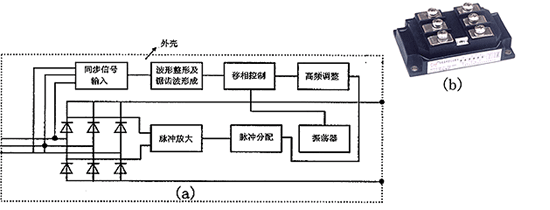
Application of Intelligent Thyristor Module in Electric Control

The application of soft starter and energy-saving operation controller is shown in Figure 5: Solid state contactors, relays, industrial electric heating temperature control, precision temperature control of various semi-body special equipment, medium and high frequency heat treatment power supplies, electric welding equipment (rectifier welding machine, secondary rectifier welding machine, inverter welding machine) laser power supply, Excitation power supply, electroplating, electrolysis power supply, mechanical and electronic equipment power supply, urban trackless, electric traction, port ship crane, fan, water pump, rail crane, gantry planer, large crane drive, ultra-low frequency molten steel, mixing power supply, papermaking, textile. Urban water supply, sewage treatment, etc., it can be said that the electrical control ITPM ​​in the power distribution system has an effect. 3. The application significance of ITPM ITPM ​​is the concentrated embodiment of the digitalization, intelligence and modularization of power electronic products, which highly demonstrates the role of modern power electronic technology in electrical control. ITPM can be used not only in more complicated control situations, but also in general switch control situations, which is its major advantage. Due to its high switching speed and arc-free shutdown and other excellent characteristics, this will improve the quality and performance of the control. Greatly improved. The extensive and large-scale application of ITPM ​​saves a lot of metal materials and greatly reduces the volume of its control system. It can also make very complicated multiple electrical control systems very simple. Centralized computer control is used to realize information management, and operation and maintenance costs are very low. The energy saving effect of ITPM ​​is very obvious, which is of great significance to environmental protection. Fourth, concluding remarks The series of ITPM ​​developed and produced by Linzi Yinhe High-Tech Development Co., Ltd. has been widely used due to its superior performance and has shown obvious social and economic benefits. It is a substitute product for traditional thyristor devices. With a wide range of applications and a broad market, it is a very ideal new generation of electrical control products. With the low-cost and large-scale entry of ITPM ​​into the market, traditional electrical control products and technologies will undergo tremendous changes and enter a new era of electrical control of power electronics.
New trends in the development of power semiconductor modules
New trends in the development of power semiconductor modules

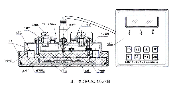
However, with the increase of module frequency and power, the general IGBT module structure with large internal parasitic inductance can no longer meet the needs of applications. In order to reduce the assembly parasitic inductance inside the module and minimize the overvoltage generated by the device during switching to meet the needs of FM high-power IGBT module packaging, ABB has developed a planar low-inductance module (ELIP) as shown in Figure 3. ). The main difference between this structure and the general traditional structure is: (1) It uses a lot of wide and thin copper sheets to overlap to form the emitter terminal and the collector terminal. When installed, it is parallel to the module copper base plate and is of equal length. The parallel wires are directly connected from the IGBT emitter to the emitter terminal, and the collector terminal is connected to the DBC board space position, thereby eliminating mutual inductance, limiting the proximity effect, and reducing the internal parasitic inductance; (2) many parallel connections Both the IGBT and FWD chips are soldered on the DBC board without graphics, and the emitter of the IGBT and the anode of the FWD are soldered with molybdenum buffer sheets. The current distribution is consistent with the rectified voltage conditions, which is beneficial for the module chip to work at the same temperature, which greatly improves the output and reliability of the module; (3) The module adopts a stacked design, which combines upper and lower insulation layers, upper and lower electrode terminals and printed circuits The plates are stacked on each other and glued together (to avoid air bubbles when bonding), which can be cycled well with temperature, without considering the so-called welding stress, that is, the so-called "S"-shaped electrode design. Since the IGBT of the MOS structure is voltage-driven, the driving power is small, and IC can be used to drive and control, and then developed to the IGBT chip, fast diode chip, control and drive circuit, overvoltage, overcurrent, overheating and undervoltage The intelligent IGBT module (IPM), which is packaged in the same insulating housing such as protection circuit, clamping circuit and self-diagnostic circuit, creates devices for high frequency, miniaturization, high reliability and high performance of power electronic inverters The foundation also simplifies the design of the complete machine, reduces the design, development and manufacturing costs of the complete machine, and shortens the time to market for the complete machine product. Because the IPM adopts a standardized grid control interface with logic level, the IPM can be easily connected to the control circuit board. The self-protection ability of IPM in the event of a fault reduces the damage of the device during development and use, and greatly improves the reliability of the whole machine.
Principle and Application of Double Closed Loop DC Speed Control Module
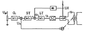
Principle and Application of Double Closed Loop DC Speed Control Module

4. Concluding remarks The system is designed in the form of modules: high integration, small size, convenient wiring, simple adjustment, safe and reliable operation, and versatility, that is, the same module has the same parameters and is very convenient to use.
Digital Intelligent Motor Control Module
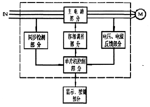
Digital Intelligent Motor Control Module

10. It is necessary to adjust the starting characteristics conveniently. It can be seen from the above that the digital intelligent motor control module integrates motor starting, energy-saving operation, and protection. The outstanding features are small size, strong functions, easy installation, simple operation, maintenance-free, and high reliability. It is an ideal replacement product for traditional starting equipment. references: 1, "Semiconductor Inverting Technology" (2nd Edition) Shanghai Machinery Technical College Mo Zhengkang Chief Editor 2, "Computer Control Technology and Application" Xiangtan Institute of Mechanical and Electrical Technology, Harbin Institute of Technology Weihai Branch Liu Guorong, Liang Jingkai Editor-in-Chief 3, "Intelligent Motor Control Module Instruction Manual" (version 2) Zibo Linzi Yinhe High-Tech Development Co., Ltd.
Function and application of intelligent motor control module
Function and application of intelligent motor control module

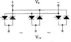
Fourth, the experimental situation and practical application introduction We have actually measured and recorded an intelligent motor control module in use. The load used is a 18.5KW fan, and the actual measured voltage is about 390V. To make a comparison, first remove the module and start directly. After closing the air switch, the voltage immediately rises to 390V, and the current rapidly rises to 150A, lasts for a period of time, gradually decreases, and finally stabilizes at about 30A. At the same time, the sound of strong mechanical vibration generated by the fan due to the impact of large current can be clearly heard. Then connect the motor soft start control module, set it to current limit mode start, the current limit value is 90A, and turn on energy saving operation. Press the "Start" button, and it can be observed that the current rise speed is obviously slower, gradually rising to 90A, and after holding for 2 to 3 seconds, it gradually decreases to 30A. The voltage rises slowly from 0V to 390V. The starting time is 6 seconds. During the whole starting process, the motor starts smoothly, and no mechanical shock is heard. After 15 seconds, the voltage gradually drops to 355V, the current does not change, and stable operation begins. The intelligent motor control module can be widely used in various industrial fields, and its function and application fields are as follows: 1, reduce the motor starting current (generally when the AC motor is started directly, the impulse current is 5-7 times the rated current); 2. Avoid instantaneous voltage drop on the power supply line when the motor starts, which may cause malfunction of equipment and meters; 3, to prevent the moment impact when starting, causing mechanical shaft breakage or waste; 4, the motor can be started more frequently (soft starter generally allows 10 times/hour, so that the motor will not overheat); 5. It can prevent water hammer effect on pump loads and prevent pipeline rupture; 6. ​​For some process applications (such as yarn dyeing machinery), it can prevent quality problems caused by uneven dyeing due to too fast starting; 7. For some fragile container grouting production lines, it can prevent container damage; 8. The starting current needs to be controlled to reduce the impact on the machine, and it can also be adapted to the occasions of lower capacity power supply transformers (such as injection molding machines); 9. It can reduce the grid adaptation capacity and save the cost of capacity expansion; 10. It is necessary to adjust the starting characteristics easily.
Characteristics and Application of Thyristor Constant Current and Constant Voltage Module

Characteristics and Application of Thyristor Constant Current and Constant Voltage Module

(2) Application principle diagram of AC constant current and constant voltage in electroplating and electrolysis (Figure 4) (3) Application in floating superimposed linear power supply (Figure 5) This device is used for high-precision high-power linear regulated power supplies, which greatly reduces the power consumption of the GTR, greatly improves the efficiency and reliability, and can use a smaller power GTR to reduce the cost. The use of constant current and constant voltage modules not only improves accuracy, but also greatly reduces the size of the power supply.
Technical solutions for the use of thyristor constant current and constant voltage control modules

Technical solutions for the use of thyristor constant current and constant voltage control modules

Constant current and constant voltage control module (1) Frequently asked questions about the first use of the module A simple function test can be performed before the module is used. It can test the constant current function and the constant voltage function, but it is more convenient to choose the constant voltage function test. The following points are common problems when using for the first time, which may be instructive for you. ①When adjusting the given signal, the module has no current or voltage output, but the given signal and the external ±12V power supply are normal. Handle: You need to reset the module. ②In constant voltage applications, the output voltage measured with a voltmeter is not accurate or continuous. Reason: Your load is too small, change a load greater than 100w. ③In constant current application, if the given signal is small, the module will output full voltage. Treatment: You need to work at a higher current, such as 20A. ④The constant current accuracy or constant voltage accuracy of the module cannot reach the specified index. Reason: The power supply index cannot meet the requirements or the given signal is unstable. ⑤Can the constant current and constant voltage functions be used at the same time? Answer: No, it can only work alone in a constant current or constant voltage mode, or switch in order. ⑥Can the module reach the maximum nominal current value under any output voltage? Answer: No, the nominal current of the module is the maximum output current at full voltage output. The specific output current also depends on the output voltage and stability accuracy. ⑦How to choose the best working interval of the module? Answer: Module application is best when the nominal value is 20%-60%; when it is less than 20% or greater than 70%, the effect is poor. ⑧How to discharge the battery when charging the battery? Method 1: Adjust the positive and negative output polarity of the module to be opposite to that during charging. Method 2: Connect the positive pole of the module to an inductor. The polarity of the module is the same as that during charging. First adjust the module voltage to be higher than the battery pack, then slowly reduce the module output voltage to the battery discharge voltage value, and use the inverter method to complete the battery discharge . This method is suitable for professional users. ⑨The index drops when the module is used for inductive load. Reason: The voltage and current sensor processing circuit of the module may process the induced signal voltage differently from the ordinary instrument. The thyristor will produce reverse spikes during commutation, and the module processing circuit will suppress the spikes; while ordinary instruments will handle the spikes as usual, so it is a normal phenomenon, not a drop in indicators. ⑩How to find the radiator temperature test point? Method: The test point should be close to the center of the module and close to the surface of the radiator of the module housing. (2) Current selection rule ①Selection of module current The nominal current of the module is the maximum current allowed to flow through the module during normal operation. Considering the poor resistance to current impact of the thyristor, it is recommended that you leave a margin when selecting the module. Resistive load: The nominal current of the module should be 2 times of the rated current of the load. Inductive load: The nominal current of the module should be 3 times the rated current of the load: ② Conduction angle requirements: In the non-sine wave state, the current value measured by an ordinary instrument is not an effective value. The smaller current value displayed by the instrument may exceed the rated value of the module by several times. Therefore, the module is required to work at a larger conduction angle as much as possible ( Above 100 degrees). The module outputs a larger current under a smaller conduction angle (that is, the module's high input voltage, low output voltage), which will cause the module to heat up and burn.
Precautions for module selection-conduction angle requirements

Precautions for module selection-conduction angle requirements

other request: (1) When the module controls the load of the transformer, if the transformer is unloaded, the output current may be less than the holding current of the thyristor chip, resulting in a large DC component in the loop, and the fuse will be burned in severe cases. In order to avoid the above situation, a fixed resistor can be connected to the output terminal of the module. Generally, the output current of each phase is not less than 500mA (specific data can be determined according to the test situation). (2) The main electrode of the small-size module is not fastened with screws, and it is easy to be lifted and broken. When wiring, pay attention to avoiding external force or cable gravity to pull the electrode and break it. (3) It is strictly forbidden to directly crimp the copper wire of the cable on the module electrode to prevent additional heating due to poor contact. (4) The module cannot be used as an isolating switch. To ensure safety, an air switch is required in front of the input terminal of the module. (5) When measuring the working case temperature of the module, the test point should be the radiator surface close to the center of the module bottom plate. Drill a deep hole horizontally below the surface of the radiator to the center of the radiator, and insert the thermocouple probe into the bottom of the hole. It is required that the temperature of the test point should be ≤80℃.
Precautions for module selection-selection of module current specifications

Precautions for module selection-selection of module current specifications

Taking into account fluctuations in line voltage and load than normal at the start of its rated current is several times larger, and poor chip thyristor current impact resistance capability, we recommend that you set aside an appropriate margin should select the module current specifications. The recommended choices are as follows: Resistive load: The nominal current of the module should be 2 times of the rated current of the load. Inductive load: The nominal current of the module should be 3 times of the rated current of the load.
Module protection-overcurrent protection
Module protection-overcurrent protection

If you want to get safer overcurrent protection, it is recommended that users use the module with internal overcurrent protection function first. In addition, an external fast fuse, fast overcurrent relay, and sensor can also be used. Fast fuse is the simplest and most commonly used method, introduced as follows: (1) Wiring method: fast fuse is connected to the AC input end of the module, take three-phase rectifier module and single-phase AC module as examples: Three-phase rectifier module         Single-phase AC module 2) Selection of fast fuse: ① The rated voltage of the fuse should be greater than the normal working voltage on the circuit. ② The rated current of the fuse should be as small as possible under the premise that the load can work normally.
Module protection-overvoltage protection

Module protection-overvoltage protection

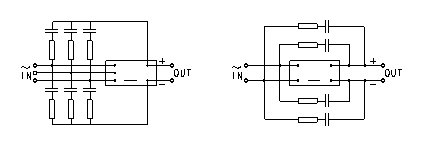
Overvoltage protection The overvoltage capability of the thyristor is extremely poor. When the reverse voltage of the component exceeds its reverse breakdown voltage, even if the time is short, the reverse breakdown of the component will be damaged. If the forward voltage exceeds the forward turning voltage of the thyristor, it will cause the thyristor to turn on hard. It not only makes the circuit work abnormally, but also reduces the forward turning voltage of the component after multiple hard turns on, or even loses the forward blocking ability and damages it. Therefore, overvoltage protection measures must be adopted to suppress the overvoltage that may appear on the thyristor. The overvoltage protection of the module is recommended to adopt the protective measures of two ways of resistance-capacitance absorption and varistor. (1) Resistance-capacitance absorption circuit When the thyristor is turned on to off, just like the switching circuit, overvoltage will be generated due to the energy released by the line inductance (mainly the transformer leakage inductance LB). Since the thyristor is conducting, carriers fill the inside of the component, so when the component is turned off, when the forward voltage drops to zero, carriers still remain inside. Under the action of the reverse voltage, these accumulated carriers instantly appear a large reverse current. The accumulated carriers disappear quickly, and then the reverse current disappears extremely fast. That is, the di/dt is extremely large. Therefore, even if the inductance L of the line connected in series with the element is small, the induced potential L (di/dt) value generated by the inductance is still very large. This potential is connected in series with the power supply voltage and applied in reverse to the element that has been restored and blocked, which may cause Reverse breakdown of thyristor. This kind of overvoltage caused by the turning off of the thyristor is called the turning off overvoltage, and its value can reach 5-6 times the peak value of the working voltage, so suppression measures must be taken. The capacitor in the resistance-capacitance absorption circuit converts the electromagnetic energy of the overvoltage into electrostatic energy storage. The resistance prevents the resonance between the capacitor and the inductance, and limits the turn-on loss of the thyristor and the current rise rate. This kind of absorption loop can suppress the overvoltage generated when the thyristor is turned on to off, and effectively avoid the breakdown of the thyristor. The installation position of the resistance-capacitance absorption circuit should be as close as possible to the main terminal of the module. That is, the lead should be short. It is best to use non-inductive resistors to achieve better protection. The wiring method is shown in the figure:
Module protection-overheating protection

Module protection-overheating protection

The quality of heat dissipation conditions is an important factor that affects whether the module can work safely. Good heat dissipation conditions can not only ensure the reliable operation of the module, prevent the module from overheating and burn, but also improve the current output capability of the module. In use, when the heat dissipation conditions do not meet the specified requirements, such as the room temperature exceeds 40℃, the outlet wind speed of forced air cooling is less than 6m/s, etc., the rated current of the module should be reduced immediately, otherwise the module will exceed the junction temperature of the chip. The allowed value is damaged. For example, when air-cooled modules should be adopted and self-cooling is adopted according to the regulations, the current rating should be reduced to 30-40% of the original value. On the contrary, if it is changed to water cooling, the current rating can be increased by 30 -40%. Reference standard for heat dissipation effect: make the temperature of the bottom plate of the module not exceed 80℃: The simplest method can be to install a temperature switch of 75℃ on the surface of the radiator near the module. In actual application, the following points should be noted: (1) The wind speed of the axial flow fan should be ≥6m/S. (2) If the module cannot reach full load, the length of the radiator can be reduced. (3) Before turning on the device, check whether all the screws of the module are firm. If they are loose, they should be tightened so that the bottom plate of the module and the surface of the radiator, as well as the electrodes of the module and the wiring terminals can be in close contact to achieve the best heat dissipation effect. . (4) When natural cooling is adopted, the air around the radiator must be able to flow naturally. (5) Because of the good heat dissipation effect of water cooling. If there are water cooling conditions, water cooling should be the first choice.

COOPERATIVE PARTNERS

合作
合作
合作
合作
合作
合作
合作
合作
合作
合作
合作
合作
银河技术

Yinhe High-Tech Development

>   ABOUT US


>   PRODUCTS


>   NEWS


>   APPLICATION


>   TECHNOLOGY


>   CONTACT


CONTACT US

Address: No. 432, Linzi Avenue, Linzi District, Zibo City,

Shandong Province

MESSAGE

Username used for comment:
客户留言
Description:
验证码

Copyright 2020 Zibo Linzi Yinhe High-Tech Development Co., Ltd.    鲁ICP备12000870号    Powered by www.300.cn