PRODUCTS
A high-tech enterprise integrating research, design, production and sales of power electronic materials (DBC ceramic
copper clad laminate), devices (power electronic modules), and power electronic devices
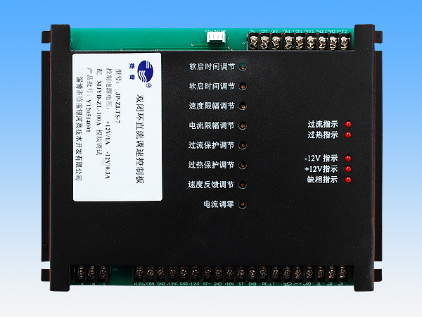
Double closed loop DC speed control board
Uses and features
1. The control board cooperates with the thyristor intelligent module to adjust the speed of the DC motor, which is widely used in the DC motor speed control system.
2. The control board has a unique design and beautiful appearance, and is equipped with a metal shield to shield interference, protect the control board, and is easy to install (if the user does not need a shield, it can not be used).
3. The control board adopts Hall sensor sampling, with high accuracy, good stability, complete isolation of sampling circuit and control circuit, safe and reliable.
4. The control board can adjust the speed loop and current loop feedback parameters according to the load characteristics to ensure the smooth operation of the motor.
5. The control board is equipped with overheating, overcurrent, and phase loss protection relays, which is convenient for users to connect alarm equipment and other protection devices.
6. The given integral link of the control panel can realize the soft start of the DC motor, and the integral time is adjustable.
7. The control board adapts to a wide range of rated input voltage of the main circuit (AC 380V, 660V, 1140V). It should be used according to the voltage marked on the nameplate.
Technical parameter
1. Control power supply: +12±0.5V /1A, -12±0.5V /0.3A.
2. Control method: DC0~10V.
3. Working environment temperature range: -25℃~+45℃; relative humidity≤85%.
4. The control panel should be dry, ventilated, far away from heat sources and strong magnetic field interference, dust-free, and non-corrosive liquid or gas.
5, the external dimension is 205mm×150mm×29mm, and the fixing hole size is 195mm×130mm (see Figure 1).
6, weight: 440 g (including shielding cover).
Specifications
1, terminal block 1 (3 sub-terminals in total)
(1) ON: Relay output port, this terminal works when phase loss protection occurs. It forms a normally open contact with the "COM" terminal.
(2) COM: Relay output port, this terminal works when phase loss protection occurs. It forms a normally open contact with the "ON" terminal, and forms a normally closed contact with the "OFF" terminal.
(3) OFF: Relay output port, this terminal works when phase loss protection occurs. It forms a normally closed contact with the "COM" terminal.
2, terminal block 2 (a total of 6 sub-terminals)
(1) ON1: Relay output port, this terminal works during overcurrent protection. It forms a normally open contact with the "COM1" terminal.
(2) COM1: Relay output port, this terminal works during over-current protection. It forms a normally open contact with the "ON1" terminal, and forms a normally closed contact with the "OFF1" terminal.
(3) OFF1: Relay output port, this terminal works during over-current protection. It forms a normally closed contact with the "COM1" terminal.
(4) ON2: Relay output port, this terminal works during overheat protection. It forms a normally open contact with the "COM2" terminal.
(5) COM2: Relay output port, this terminal works during overheating protection. It forms a normally open contact with the "ON2" terminal, and forms a normally closed contact with the "OFF2" terminal.
(6) OFF2: Relay output port, this terminal works during overheat protection. It forms a normally closed contact with the "COM2" terminal.
3, wire terminal 3 (total 3 sub-terminals)
A, B, C three-phase synchronization signal input terminal.
4, terminal 4 (total 19 sub-terminals)
(1)+12V↓: +12V output terminal. It is internally connected to the +12V of the control power supply and can be connected to the +12V input terminal of the thyristor intelligent module.
(2) CON: Output 0~10V signal. It can be connected to the control signal input terminal of the thyristor intelligent module.
(3) GND: +12V ground terminal. It is internally connected to the GND of the control power supply and can be connected to the ground input terminal of the thyristor intelligent module.
(4)+12V↑: +12V input terminal. Connect the +12V of the control power supply to provide +12V working power for the control board.
(5) GND: ±12V ground terminal. Connect to GND of control power supply.
(6)-12V↑: -12V input terminal. Connect the -12V of the control power supply to provide -12V working power for the control board.
(7)SF-: The negative signal input terminal of tachogenerator.
(8) GND: The positive signal input terminal of the tachogenerator.
Note: The maximum input DC voltage between GND and SF- is 110V.
(9)+10V: It is internally connected to +12V through a 1KΩ resistor to provide power for the control potentiometer.
(10)ST: Control signal input terminal. The input signal is DC0~10V, which requires stability and no glitches.
(11) GND: Control signal ground. It is internally connected to the GND of the control power supply.
(12)(13)RESET: Reset the port. Reset when the two terminals are shorted.
(14)(15)+ -: External temperature sensor. The thermistor type temperature sensor is recommended. Thermistor parameters are: R=50kΩ at 25°C, R=26.8kΩ at 40°C, R=18.1kΩ at 50°C, R=15kΩ at 55°C, R=12.56kΩ at 60°C, R=10.57 at 65°C kΩ, R=8.92kΩ at 70°C, R=7.55kΩ at 75°C, R=6.41kΩ at 80°C.
(16) GND: Connect internally to the GND of the control power supply.
(17)GL: Overcurrent protection indication connection terminal. The anode of the light-emitting diode can be connected externally, and the cathode of the light-emitting tube is grounded. The luminous tube lights up when protected.
(18)GR: Overheat protection indicator connection terminal. The anode of the light-emitting diode can be connected externally,
And the negative pole of the light-emitting tube is grounded. The luminous tube lights up when protected.
(19)QX: Open phase protection indication connection terminal. The anode of the light-emitting diode can be connected externally,
And the negative pole of the light-emitting tube is grounded. The luminous tube lights up when protected.
5. Four-core connector: Hall current sensor connection terminal. This terminal outputs +12V, -12V, GND current feedback signal IF.
6, potentiometer (8 in total)
(1) Potentiometer 1, 2: Soft start integral time adjustment potentiometer. Adjust clockwise to extend the integration time, and adjust counterclockwise to shorten the integration time. Potentiometer 1 changes the size of the integral signal, and potentiometer 2 changes the size of the integral constant.
(2) Potentiometer 3: Speed loop limiter adjustment potentiometer. Adjust clockwise to decrease the limit value; adjust counterclockwise to increase the limit value.
(3) Potentiometer 4: Current loop limiting adjustment potentiometer. Adjust clockwise to increase the limit value; adjust counterclockwise to decrease the limit value.
(4) Potentiometer 5: Overcurrent protection value setting. The overcurrent protection value is adjusted clockwise to increase, and the overcurrent protection value is adjusted counterclockwise to decrease. It has been adjusted before leaving the factory, users generally do not need to adjust.
(5) Potentiometer 6: Overheating protection value setting. Adjust the overheating protection value clockwise to increase, and adjust the overheating protection value counterclockwise to decrease. It has been adjusted before leaving the factory, users generally do not need to adjust.
(6) Potentiometer 7: Speed feedback signal size adjustment potentiometer. Adjust clockwise to increase the feedback signal; adjust counterclockwise to decrease the feedback signal.
(7) Potentiometer 8: Current sensor zero adjustment compensation potentiometer. It has been set before leaving the factory, and users generally do not need to adjust.
7, light-emitting diodes (5 in total)
(1) Light-emitting diode 1: Overcurrent protection indicator light.
(2) Light-emitting diode 2: Overheating protection indicator light.
(3) Light-emitting diode 3: -12V power indicator.
(4) LED 4: +12V power indicator.
(5) LED 5: Phase failure protection indicator.
Recommended Products

Yinhe High-Tech Development
MESSAGE
- After-sales service
- Hotline +86-533-7216217
- Top
Copyright 2020 Zibo Linzi Yinhe High-Tech Development Co., Ltd. 鲁ICP备12000870号 Powered by www.300.cn

