
PRODUCTS
A high-tech enterprise integrating research, design, production and sales of power electronic materials (DBC ceramic
copper clad laminate), devices (power electronic modules), and power electronic devices
Frequency converter
Product description
General technical specifications
|
enter |
Rated voltage and frequency |
S2/T2 single-phase/three-phase 220V; 50/60Hz; T4 three-phase 380V; 50/60Hz
T6 three-phase 660V; 50/60Hz; T11 three-phase 1140V; 50/60Hz
|
|
|
Allowable voltage range |
+/-15% voltage imbalance rate <3%; frequency ±5% |
||
|
lose
Out
|
Maximum output |
S2/T2/Three-phase 220V; T4 three-phase 380V; T6 three-phase 660V; T11 three-phase 1140V |
|
|
frequency |
0Hz ~ 500Hz |
||
|
Overload capacity |
G type machine: rated current * 150% for 1 minute, rated current * 180%; 2 seconds; P type machine: rated current * 120% for 1 minute, rated current * 150%; 2 seconds. |
||
|
control
system
special
Sex
|
way to control |
V/F control |
|
|
Output
frequency
Precision
|
Analog setting |
±0.2% of maximum output frequency |
|
|
Digital setting |
±0.01Hz |
||
|
External pulse setting |
±0.1% of maximum output frequency |
||
|
RS485 setting |
±0.01Hz |
||
|
V/F curve (voltage frequency characteristic) |
The reference frequency is arbitrarily set at 5~500Hz, and you can choose constant torque, decreasing torque 1, decreasing torque; 2. Three types of curves and custom curves. |
||
|
Torque boost |
The lifting torque can be set according to actual needs, 0~20% of the rated output |
||
|
Automatic energy-saving operation |
According to the load condition, the V/F curve is automatically optimized to realize energy-saving operation. |
||
|
Acceleration and deceleration time setting |
0.1~6000 seconds can be set continuously, S-type and linear mode are optional |
||
|
brake |
Dynamic braking |
Motor output rated torque*75% |
|
|
DC braking |
It can be selected separately when starting and stopping, action frequency 0~15Hz, motor rated current×(0~100%), action time 0~20.0 seconds, or continuous action |
||
|
Automatic current limiting function |
Fast current automatic suppression capability to prevent frequent over-current faults during acceleration and under impact load |
||
|
Voltage stall prevention |
Ensure that no overvoltage occurs during deceleration |
||
|
Carrier adjustment |
Carrier frequency 1.5KHz ~ 15.0KHz continuously adjustable to minimize motor noise |
||
|
Frequency setting channel |
Analog input |
Panel potentiometer, DC voltage 0~10V, DC current 0~20mA (upper and lower limit optional) |
|
|
Digital setting |
Using the operation panel |
||
|
Pulse input |
0~50.000KHz (upper and lower limit optional) |
||
|
RS485 |
PC setting |
||
|
Start signal |
Forward, reverse, start signal self-holding (three-wire control) optional |
||
|
Timer, counter |
One built-in timer and one counter to facilitate system integration |
||
|
Multi-speed/PLC control function |
When using external terminals to select multi-speed control, up to 15 speeds; programmable multi-speed control (PLC) up to 7 speeds, the running direction and running time of each speed can be set separately |
||
|
Swing frequency function |
Suitable for textile occasions |
||
|
Built-in PID control |
It can easily form a simple closed-loop control system without additional PID controller. |
||
| output signal |
Switch signal (Y1, Y2 and relay T) output |
When the inverter is running, the frequency reaches, frequency level detection, overload alarm, external fault shutdown, frequency upper limit arrival, frequency lower limit arrival, undervoltage stop, zero-speed operation, programmable multi-speed status, internal counter arrival, internal timer arrival, malfunction |
|
|
Analog output |
Output frequency, output current, output voltage, etc. can be connected with voltmeter and frequency meter | ||
|
display |
operating
panel
display
|
Operating status |
Output frequency, output current, output voltage, motor speed, set frequency, PID setting, PID feedback, module temperature, running time accumulation, analog input and output, terminal input status, etc. |
|
Alarm content |
The last six fault records, the output frequency, set frequency, output current, output voltage, DC voltage, module temperature, terminal status, and accumulated operating time when the last fault tripped 8 operating parameter records |
||
|
Protection/alarm function |
Overcurrent, overvoltage, undervoltage, phase loss, electronic thermal relay protection, overheating, short circuit, overload |
||
|
ring
territory
|
Ambient temperature |
-10ºC to +50ºC (no freezing) |
|
|
Ambient humidity |
Below 90% (no frost) |
||
|
surroundings |
Indoor (no direct sunlight, no corrosion, no flammable gas, no oil mist, dust, water vapor, water droplets, etc.) |
||
|
altitude |
Less than 1000m |
||
|
structure |
Protection level |
IP30 |
|
|
cooling method |
Forced air cooling |
||
|
Installation method |
Wall-mounted / cabinet |
||
Mechanical parameters
|
Inverter model |
Installation size |
Dimensions |
Mounting holes |
Weight (kg)≈ |
|||
|
A(mm) |
B(mm) |
W(mm) |
H(mm) |
D(mm) |
|||
|
QY8000-0004G-S2 |
115 |
160 |
125 |
170 |
118 |
Φ4 |
1.2 |
|
QY8000-0007G-S2 |
|||||||
|
QY8000-0015G-S2 |
110 |
160 |
125 |
170 |
145 |
Φ4 |
1.5 |
|
QY8000-0022G-S2 |
|||||||
|
QY8000-0007G-T4 |
110 |
160 |
125 |
170 |
145 |
Φ4 |
1.5 |
|
QY8000-0015G-T4 |
|||||||
|
QY8000-0022G-T4 |
|||||||
|
QY8000-0037G/0055P-T4 |
135 |
247 |
150 |
253 |
150 |
Φ5 |
3 |
|
QY8000-0055G/0075P-T4 |
|||||||
|
QY8000-0075G/0110P-T4 |
|||||||
|
QY8000-0110G/0150P-T4 |
225 |
375 |
250 |
400 |
195 |
Φ8 |
7.8 |
|
QY8000-0150G/0185P-T4 |
|||||||
|
QY8000-0185G/0220P-T4 |
|||||||
|
QY8000-0220G/0300P-T4 |
|||||||
Operation and operation instructions
4.1 Explanation
In the following chapters, the terms describing the control, operation and status of the inverter will be used many times. Please read this chapter carefully to help understand and use the functions mentioned later.
4.1.1 The run command channel of the inverter
It refers to the physical channel through which the inverter accepts operations such as run, stop, and jog. There are three types:
Operation panel: control via the RUN, STOP and JOG keys on the operation panel
External terminals: control via X1 (FWD), X2 (REV), COM, X? (three-wire control)
485 interface: start and stop control through the upper computer
The command operation channel selection can be determined by P0.02. When the external terminal is selected for control, the external terminal control mode must be further determined through P3.00, including two-wire 1, two-wire 2 and three-wire control
4.1.2 Inverter frequency given channel
QY8000 has 8 independent frequency given channels:
Panel potentiometer
Panel
key given
terminal UP/DW setting
Analog voltage V1 given
Analog voltage V2 given
Analog current II setting
pulse setting
RS485 given
8 kinds of frequency reference channels can also be used as the final frequency reference after a variety of combinations (see P4.34 for details)
4.1.3 Working status of the inverter
The working status of QY8000 is divided into shutdown status, running status and fault status.
Stop state: After the inverter is powered on and initialized, if no running command is input to the inverter or a stop command is input during running, the inverter will enter the stop command.
Running status: After receiving the running command, the inverter enters the running status.
Fault state: The inverter will be notified of a fault or an external fault, and the inverter will block the output (the output voltage is 0 at this time) and is in a fault state.
4.1.4 Operation mode of the inverter
There are 6 operation modes of QY8000, which are divided into the following order according to priority: swing frequency >> jog >> PLC >> multi-speed >> PID >> normal operation.
Swing frequency operation: specially designed for textile occasions, please refer to the explanation of P7 function group for details.
Jog operation: After the inverter receives the jog operation command, it runs at the jog operation frequency.
PLC operation: When the PLC function selection is valid, the inverter will select the PLC operation mode, and the inverter will operate according to the predetermined operation mode.
Multi-speed operation: The inverter selects the operating frequency of the inverter through the external terminal Xi (function number 1, 2, 3, 4).
Closed-loop operation (PID): PID function selection is valid, and the inverter will run in closed-loop operation mode, that is, the reference and feedback will determine the output frequency through PID adjustment.
Normal operation: simple open loop operation mode, the operation frequency is determined according to the frequency setting channel determined by P0.01.
6 kinds of operation modes determine the 6 kinds of frequency sources of the inverter.
4.2.3 Digital display area
4-digit LED display, can display various monitoring data such as set frequency, output frequency and alarm code.
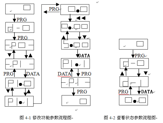
4.3 Operation process
4.3.1 Function parameter setting
The three-level menus are
1, function code parameter (first level menu);
2, function code label (second-level menu);
3. Function code setting value (three-level menu).
4.3.2 Monitoring parameter query
There are two situations for monitoring parameter query. In one situation, in the monitoring state, press "" to cycle through the three most commonly used parameters (determined by P4.28, P4.29, and P4.30); the other situation , View the state parameters that the user cares about by viewing the d parameter.
Example: View the inverter d-01 (inverter output current value) value, as shown in Figure 4-2.
4.3.3 Fault reset
After the inverter fails, the inverter will prompt related fault information. The user can reset through the "STOP/RESET" on the keyboard or the external terminal function (P3 group setting), and the inverter will be in the standby state after the fault is reset. If the inverter is in a fault state and the user does not reset it, the inverter is in the running protection state and the inverter cannot run.
4.4 Inverter operation
4.4.1 Power-on initialization
In the inverter power-on process, the system first initializes, the inverter's DC bus voltage goes from low to high, and the LED displays "SA". When the voltage value reaches a certain value, the inverter is in the standby state and the LED displays "0".
4.4.2 Operation of the inverter
The inverter can be started by keyboard control, external terminal start or communication start (see P0. 02). When the inverter is running, the user can monitor 22 state variables (see parameter d).
Specification
5.1 Basic operating parameters (P0 parameter)
QY8000 series inverter adopts G/P in one mode, that is, it is used for constant torque load (G type) and the adapted motor is one gear lower than when it is used for fan and pump load (P type)
P0.01 Frequency channel selection Setting range: 0, 9
Select the input channel of frequency command:
0: Panel potentiometer The operating frequency is set by the potentiometer on the operation panel.
1: P0.03 setting When selecting [P0.01]=1, by pressing the up and down buttons on the operation panel, the frequency value in the P0.03 parameter can be changed and the running frequency can be set.
2: V1 The operating frequency is set by the external analog voltage input terminal V1 (0 ~ 10V).
3: V2 The operating frequency is set by the external analog voltage input terminal V2 (0~10V).
4: II The operating frequency is set by the external analog current input port II (0 ~ 20mA).
5: UP/DW terminal increment and decrement control
The running frequency is set by the external control terminals UP/DW (UP and DW control terminals are selected by parameters P3. 01 ~ P3.07). When UP-COM is closed, the running frequency increases, and when DW-COM is closed, the running frequency decreases. When UP and DW are closed or disconnected with COM at the same time, the operating frequency remains unchanged. The frequency rises and falls according to the set acceleration and deceleration time.
6: External pulse signal
The running frequency is set by the external pulse signal, and the pulse input terminal is selected by parameter P3.07 (X7).
7: RS485 interface
Receive the frequency command from the upper computer through the RS485 interface. When the upper computer is used to set the frequency or the unit is set as a slave in the linkage control, this mode should be selected.
8: combination given
The running frequency is determined by the linear combination of each set channel, and the combination mode is determined by parameter P4.34.
9: External terminal selection
The frequency setting channel is selected by the external terminal (the selected terminal is determined by the parameters P3.01~P3.07). The corresponding relationship between the terminal status and the frequency setting channel is shown in the following table:
|
Frequency setting selection terminal 3 |
Frequency setting selection terminal 2 |
Frequency setting selection terminal 1 |
Frequency setting channel |
|
0 |
0 |
0 |
0 |
|
0 |
0 |
1 |
1 |
|
0 |
1 |
0 |
2 |
|
0 |
1 |
1 |
3 |
|
1 |
0 |
0 |
4 |
|
1 |
0 |
1 |
5 |
|
1 |
1 |
0 |
6 |
|
1 |
1 |
1 |
7 |
Fault handling and abnormal countermeasures
P0.02 Operation command channel selection Setting range: 0 ~ 4
0: The operation command is controlled by the operation panel
1: The running command is controlled by external terminals, and the keyboard STOP is invalid
2: The running command is controlled by external terminals, and the keyboard STOP is valid
3: The operation command is controlled by RS485 communication, and the keyboard STOP is invalid
4: The operation command is controlled by RS485 communication, and the keyboard STOP is valid
When the input frequency channel selection panel is digitally set ([P0.01]=1), the output frequency of the inverter is determined by this value after adding slip compensation. In the status monitoring mode, press the key or key on the operation panel to directly modify this parameter
Acceleration time refers to the time required for the output frequency to accelerate from 0Hz to the reference frequency set by P0.06. Deceleration time refers to the time required for the output frequency to decelerate from the reference frequency value set in P0.06 to 0Hz.
Acceleration/deceleration mode 0: straight line. Linear acceleration and deceleration are adopted by most loads; 1: S curve. S-curve acceleration and deceleration are mainly provided for the need to reduce noise and vibration and reduce the load of start-stop shock during acceleration and deceleration. As shown in Figure 5.1-1.
Maintenance
All possible failure types of QY8000 are summarized in Table 6-1. After the inverter fails, the user can deal with it according to the instructions in the table before seeking service, and record the processing process and phenomenon in detail. If the fault cannot be solved, you can seek the support of the manufacturer or local office.
Recommended Products


Yinhe High-Tech Development
MESSAGE
- After-sales service
- Hotline +86-533-7216217
- Top
Copyright 2020 Zibo Linzi Yinhe High-Tech Development Co., Ltd. 鲁ICP备12000870号 Powered by www.300.cn